CAD & Engineering Drafting
November 2025
Outcome A twelve-sheet dimensioned drawing package for a full assembly, and designs that left the screen — 3D-printed tools in daily use.
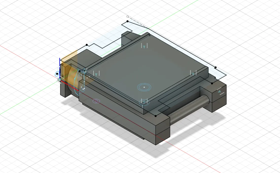
A body of mechanical design and drafting work — from single turned parts to multi-part assemblies with complete engineering drawing packages, plus designs that left the screen and became real tools. The gallery below walks through the highlights.
The final assembly
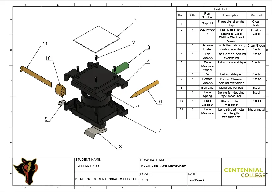
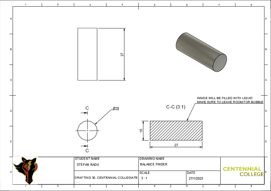
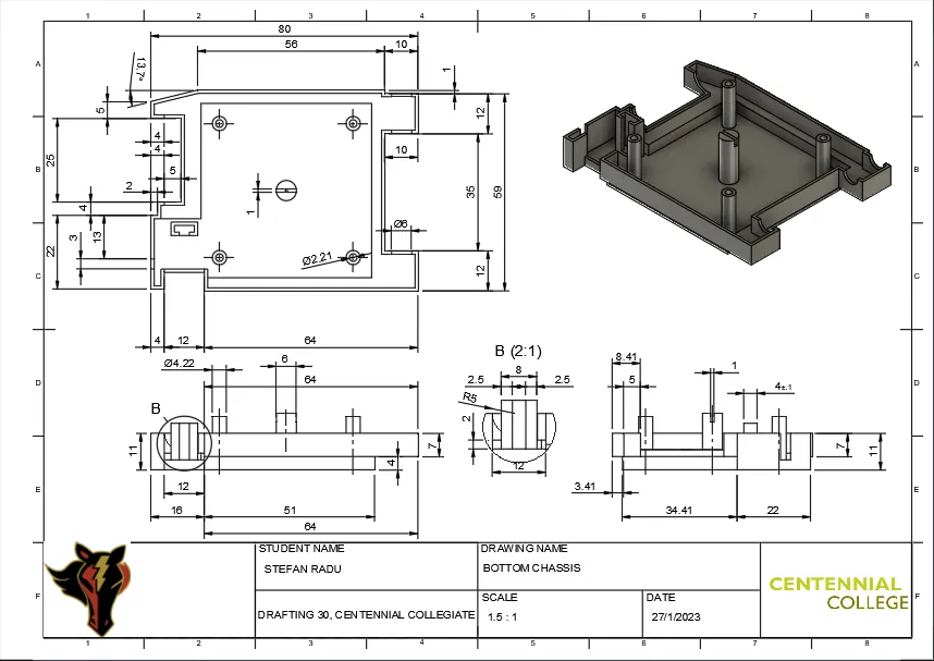
The biggest piece: a multi-part machine assembly modelled in Fusion 360 and documented across twelve drawing sheets — every component fully dimensioned, plus assembly views with a bill of materials. The rendered animation below is straight out of Fusion 360:
The measuring tool
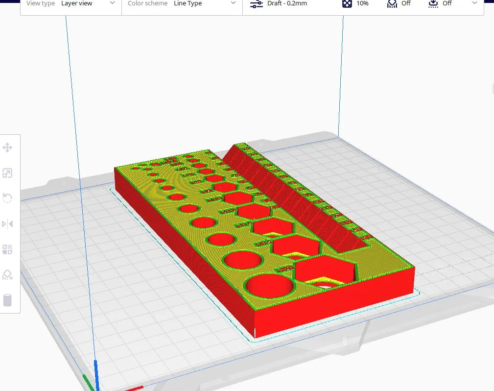
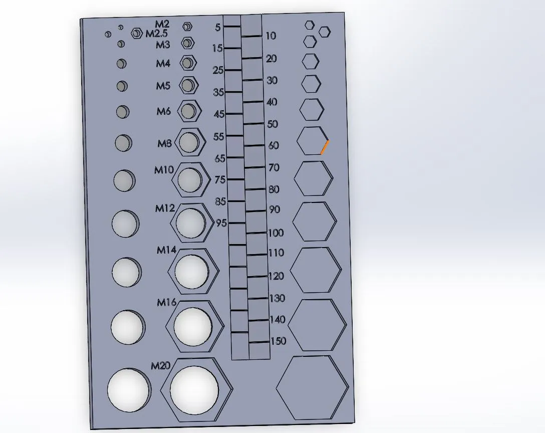
A design that became a real thing: a bolt-and-thread measuring tool modelled in SolidWorks, exported to STL, sliced, and 3D printed. It went through several printed iterations to get the metric hole sizes right — the version in the gallery is the one that now lives in the toolbox and gets used every time hardware needs sorting. The same design process produced the bolt-and-nut sorter the FSAE team uses.
Machine components
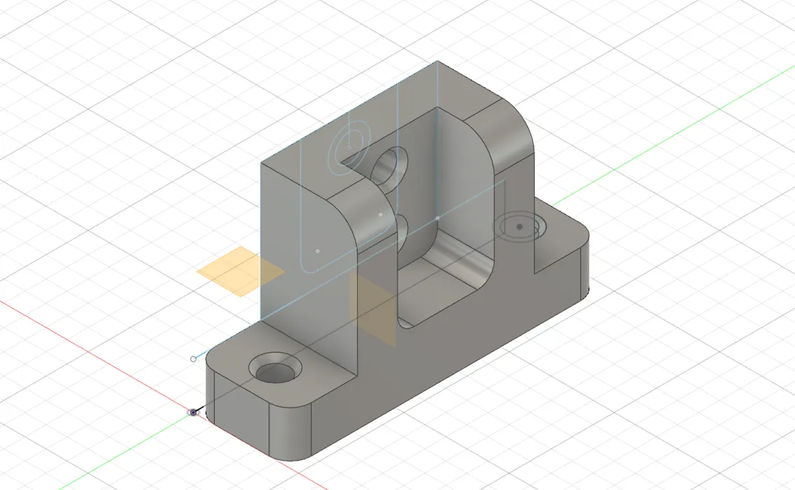
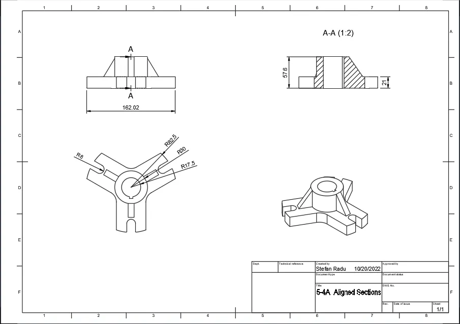
Coursework and practice parts, each with proper drawings: lathe turret spindles, tapered bushings, clutch spigots, vice bases, starter brackets — full, half, offset, and aligned section views, auxiliary views, and fastener callouts.
AutoCAD
A separate body of 2D drafting work in AutoCAD: dimensioning exercises, full sections, isometrics — and some fun ones, including a chess piece, sacred geometry constructions, and a Master Chief drawing.
Tooling
Fusion 360 (fluent), AutoCAD (fluent), SolidWorks (intermediate), Revit (intermediate).
Gallery
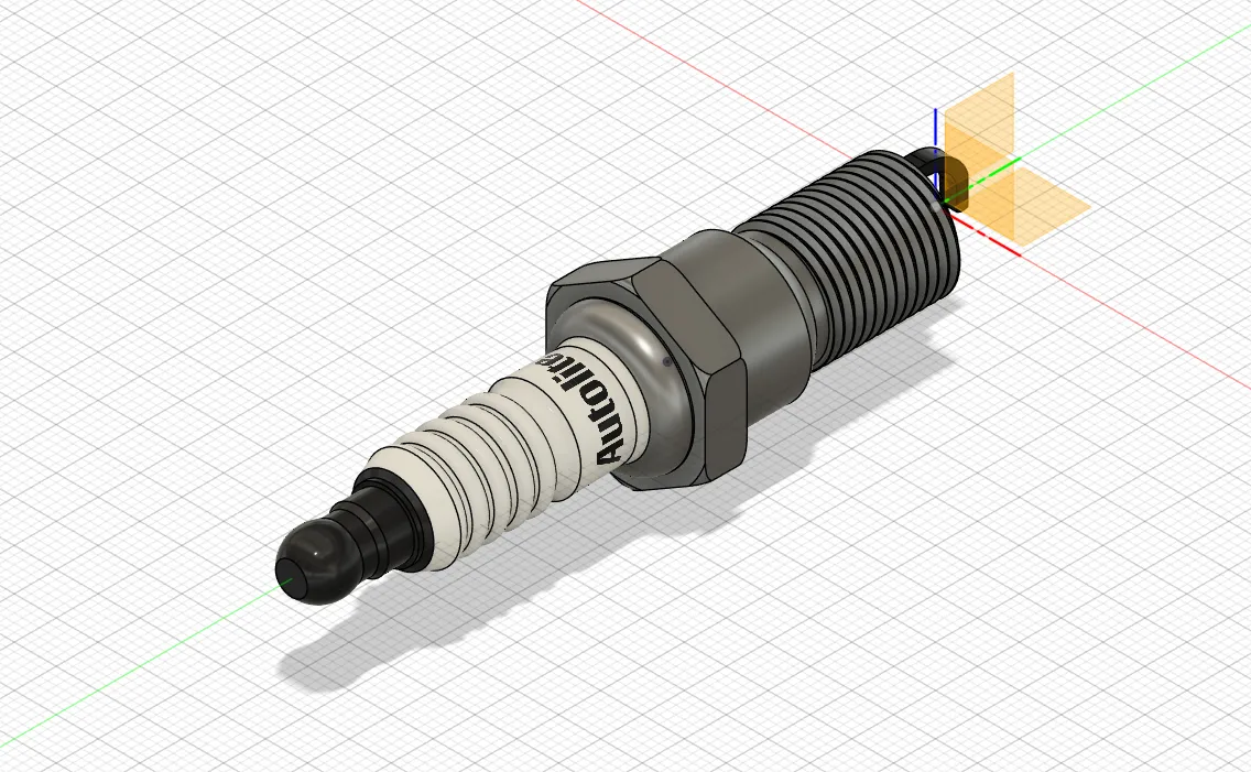
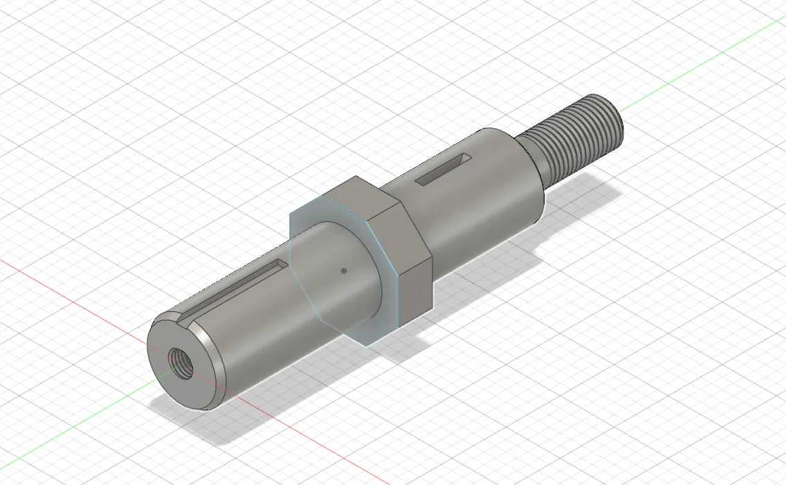
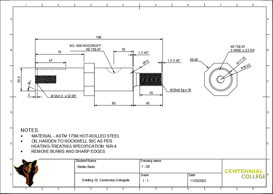
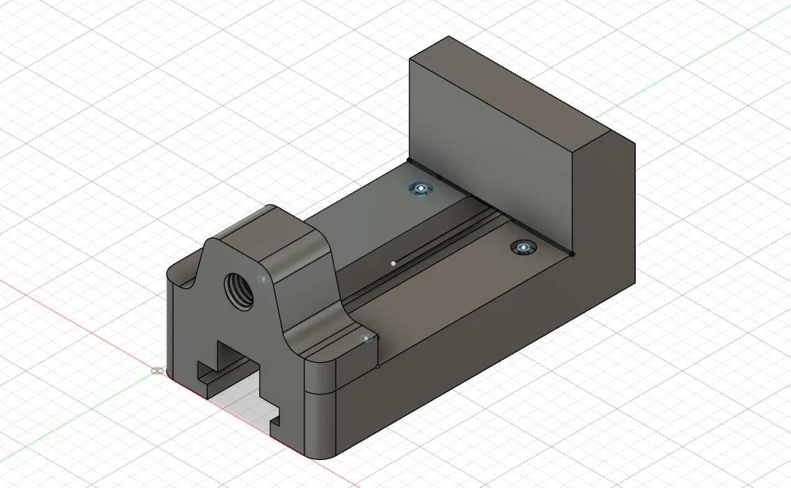
1 / 12